
Line Follower
Overview & Purpose
A line follower robot is an automated vehicle that follows a visual line embedded on the surface. This visual line is a path on which the line-follower robot runs. Generally, it uses a black line on a white surface.
Line follower robots are used to assist the automated production process. They are also used in military applications, human assistance purposes, delivery services, etc.
Education Standards
- Integration of Multiple Discipline Learnings
- Hands – On Experience
- Enjoyable and creative learning Experience
Objectives
- Science: The concept of the line follower robot is related to light. Here, we use the behavior of light on the black-and-white surface. The white color reflects all the light that falls on it, whereas the black color absorbs the light.
Students learn about the physics of motion, including concepts like speed, acceleration, and inertia, as they design a robot that follows a predefined path. - Technology: In this line-follower robot, we use IR transmitters and receivers (photodiodes). They are used to send and receive the lights. When IR rays fall on a white surface, they are reflected toward the IR receiver, generating some voltage changes.
Students gain hands-on experience in programming microcontrollers or computers to control the robot’s movements based on sensor feedback. - Engineering
- Mechanical Design:
- Chassis: The chassis or frame of the robot is designed to house all the necessary components. It should be sturdy and well-balanced to ensure stability during movement.
- Wheels and Motors: Selection of appropriate wheels and motors is crucial for achieving accurate and controlled movement. Motors drive the wheels, and the type of wheels used affects traction and maneuverability.
- Electrical Engineering:
- Microcontroller: A microcontroller, such as Arduino or Raspberry Pi, serves as the brain of the line follower. It processes sensor data and controls the motors based on programmed algorithms.
- Mechanical Design:
- Mathematics: To find the Steering value and to ensure smooth movements of our robot we need to use differentiation and integration for calculating errors with respect to time and geometry to calculate angles, Distances and turning Radii.
- Arts: Creative Designs students have the opportunity to be creative in designing the appearance of their robots. They can add artistic elements, such as custom decorations or themed designs, making the project visually engaging.
Scientific Principle
Reflection and Light Sensing: Line follower robots typically use infrared (IR) sensors to detect lines on the surface. These sensors emit infrared light, and the reflection of this light is used to determine the contrast between the line and the surrounding surface.
Inertia and Motor Control: The movement of the robot involves the principles of inertia and motor control. Inertia refers to the resistance of an object to change its state of motion, and motor control is used to precisely control the robot’s movement.
Mathematical Principle
Steering Calculation:
To ensure the smooth movement of the robot we calculate the steering value in a line follower robot is a parameter that determines how much the robot should turn or adjust its direction to stay on the desired path (usually a line on the floor) this is combinedly called P.I.D (Proportional – Integral – Derivative ) Controlalgorithm.
Proportional Term:
Error Calculation: Measure the deviation or error of the robot from the center of the line. This is the difference between the desired position (center of the line) and the actual position (where the sensors detect the line).
Proportional Gain (Kp): The proportional term is responsible for providing an immediate response to the current error. Multiply the error by a proportional gain (Kp). The proportional term contributes to the immediate correction based on the current error.
P= Kp × Error
Integral Term:
Accumulate the error over time and multiply it by an integral gain (Ki). The integral term contributes in correcting long term errors.
I = Ki × ∑ Error
Derivative (D) Term:
Error Rate of Change: Measure the rate of change of the error with respect to time . This helps in predicting future errors based on the current movements.
Derivative Gain (Kd): Multiply the rate of change of error by a derivative gain (Kd), This helps in stabilizing the control system.
D = Kd × dError / dt
Steering Value Calculation:
Steer = P + I + D
Components Used in Line Follower Robot
- Arduino Uno
- IR sensor
- L293D motor driver
- BO motor
- Wheels
- Lithium-ion battery
- Jumper cables
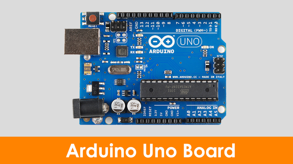
Arduino Uno
Arduino Uno is an 8-bit ATmega328P microcontroller. To support the microcontroller, it uses components such as a crystal oscillator, serial communication, voltage regulator, etc. It has 14 digital I/O pins( 6 pins can be used as PWM pins). It has six separate analog input pins, a USB connection, a power barrel jack, an ICSP header, and a reset button
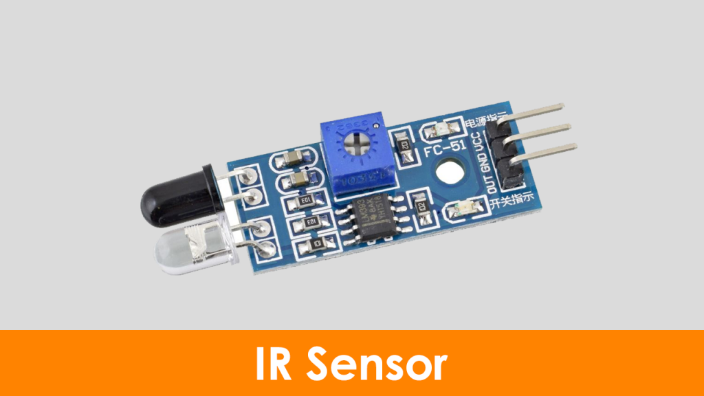
Infrared Sensor:
Here, the IR LED is an emitter, and the IR photodiode is a detector. An IR LED emits the IR light, and the photodiode is sensitive to this IR light. When IR light falls on the photodiode, the output voltages and the resistances will change in proportion to the magnitude of the received IR light.
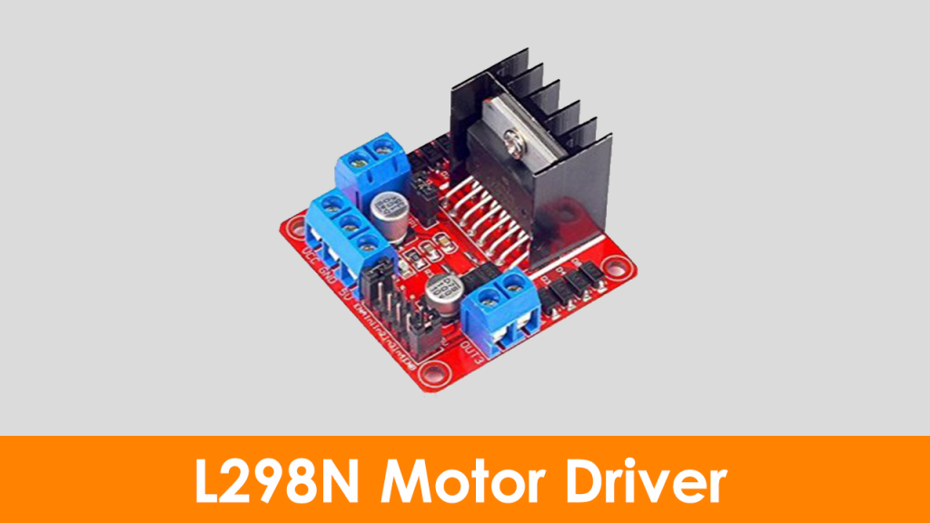
L298N Motor Drive
This L298N motor driver is a high-power motor driver module. It is used for driving DC and stepper motors. This motor driver consists of an L298N motor driver IC and a 78M05 5V voltage regulator, resistors, capacitor, power LED, and 5V jumper in an integrated circuit.
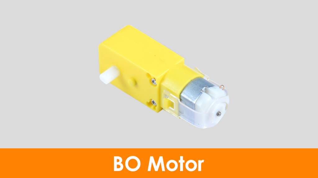
BO Motors
BO series linear motors provide good torque and rpm at lower operating voltages. The BO motors are available in single-shaft, dual-shaft, and DC plastic gear BO. These motors consume a low current. In this project, we have used four single-shaft BO motors.
Lithium-ion Battery
A lithium-ion battery provides 3.7V in storage mode and 4.2V in full charge mode. In this project, we have connected two lithium-ion batteries in series so that the total battery voltage will be 8.4V at full charge.

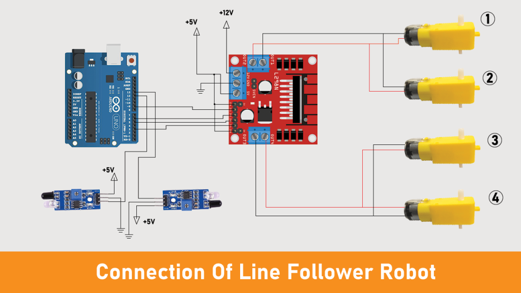
Connection Diagram of Line Follower Robot
We have used four BO motors. Motors 1 and 2 are connected to the first channel of L298N, whereas motors 3 and 4 are connected to the second channel of the motor driver. IN1, IN2, IN3, and IN4 pins are connected to pins 9, 6, 5, and 3 of the Arduino Uno. Here, we have used the jumper between +5V and the enable pins (EN1 and EN2). You can remove it and make the external connection, as shown in the below image.

Responses